Resolver Control Transmitter & Resolver Control Transformer
- In this article, principle, construction and working of resolver control transmitter and resolver control transformer is given.
- Synchro is often referred as cousin of resolver.
- People often interchange term for resolver as motion feedback sensors, transducer sensors, encoders and rotary position sensors.
- The application of resolver in the military, product packaging plants and stamping press lines.
- There are two types of resolvers
- Resolver control transmitter
- Resolver control transformer
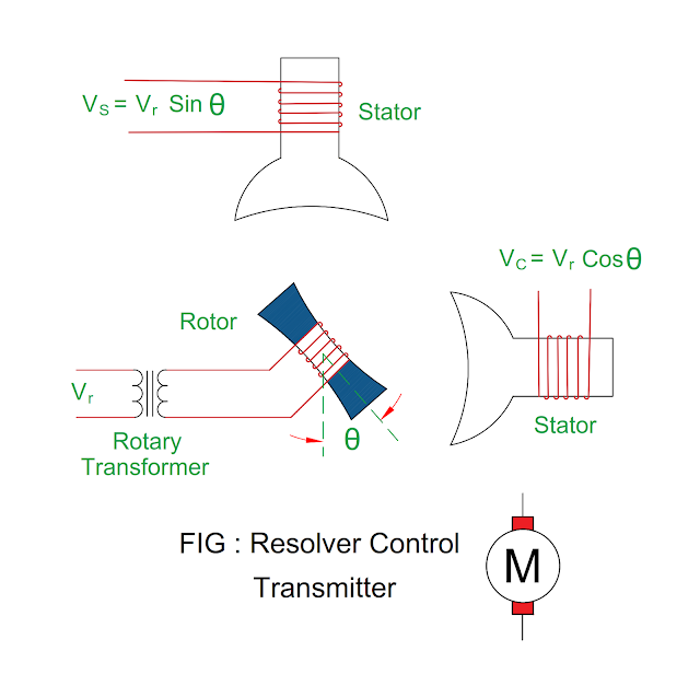
Resolver Control Transmitter
Principle of Resolver Control Transmitter
- It is a rotary transformer in which magnitude of stator energy varies sinusoidally as the shaft rotates.
Construction of Resolver Control Transmitter
- There are two windings in the resolver in which one primary winding or reference winding and two secondary windings ( SIN winding and COS winding ).
- The primary winding or reference winding is embedded in the rotor and supply given to it via rotary transformer.
- There are two windings embedded in stator slots which are at 90 degree mechanically displaced.
- An alternating supply is given to reference winding by rotary transformer, no need of brushes and slip rings.
Working of Resolver Control Transmitter
- When alternating supply ( Vr ) is given to reference winding, voltage induced in the stator SIN winding and stator COS winding.
- The two windings are displaced at 90 degree so it is called as SIN winding and COS winding.
- The magnitude of the induced voltage depends upon multiplication of reference voltage and SIN or COS angle of input shaft from electrical zero ( EZ ) point.
VS
= Vr Sin θ
VC
= Vr Cos θ
The
rotor shaft position θ depends upon SIN winding and COS winding.
Tan
θ = VS / VC
The
ratio of two voltage represents absolute position of shaft.
Shaft position of rotor θ = Tan – 1 ( VC / VS )
Electrical Zero Position
- When rated alternating voltage is given to the rotor winding at rotor initial position ( zero degree ), zero voltage induced in the stator SIN winding ( SIN 0 degree = 0 ) and maximum voltage induced in the stator COS winding ( COS 0 degree = 1 ), this position is called as electrical zero ( EZ ) position.
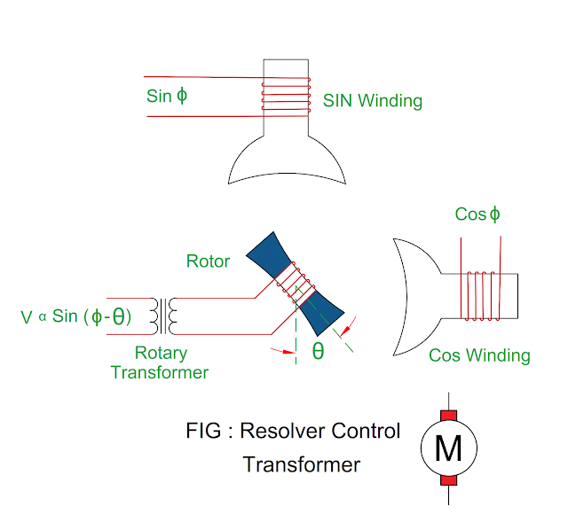
Resolver Control Transformer
- It has two stator winding ( SIN winding and COS winding ) and one rotor winding.
- The rotor output voltage is directly proportional to sine of angle difference between input angle of stator and mechanical position of shaft.
- The rotor voltage is directly proportional to Sin ( Φ – θ )
Where θ =
Reference position of shaft
Φ = Stator input angle
|
You may also like to read these articles
: Why Crushed Rock is used at earth
surface in substation? Important Indian Electricity Rule
NO 50 |


No comments:
Post a Comment