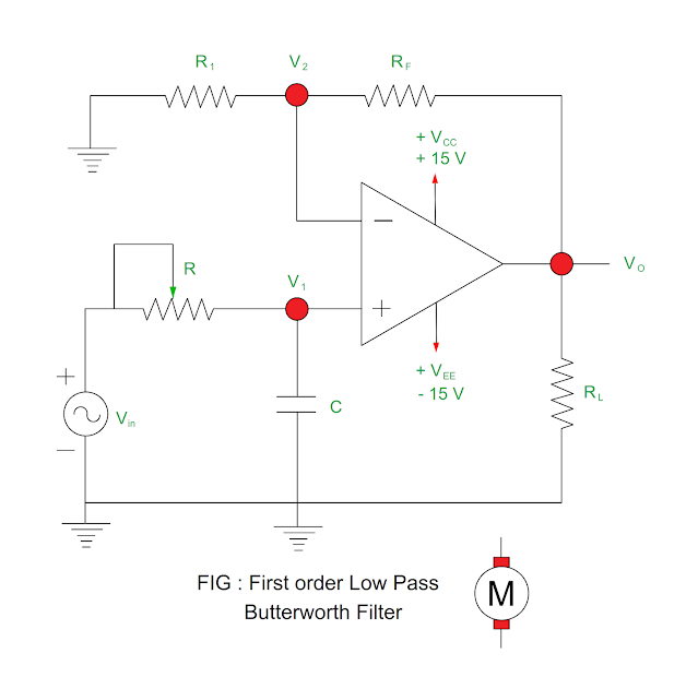
In this article, First order Low Pass Butterworth
Filter circuit, Second order Low Pass Butterworth Filter circuit, gain of the
filter and its frequency response is given.
First order Low Pass Butterworth Filter
- It is a filter which has nearly ideal response, flat passband as well as flat stop band.
- As both passband and stop band are flat, it is also called as flat – flat filter.
- The first order low pass Butterworth filter employs RC circuit for filtering.
- The non – inverting amplifier configuration is used for it. The gain of the filter depends upon RF and R1.
Input voltage at
the non – inverting terminal
V1 = - jXC / ( R – jXC ) ( Vin )
= [ - j / 2πfC / (
R – j / 2πfC ) ] ( Vin )
= [ - j / ( R2πfC – j
) ] ( Vin )
= [ 1 / ( 1 + R2πfC ) ] ( Vin )…… ( 1 )
Output voltage
Vo = (
1 + RF / R1 ) V1……. ( 2 )
From equation ( 1
) and ( 2 )
Vo = (
Vin )( 1 + RF / R1 ) / ( 1 + R2πfC )
Vo / Vin
= ( 1 + RF / R1 ) / ( 1 + R2πfC )
Vo / Vin = AF
/ [ 1 + j ( f / fH ) ]
Where
|
Gain
of the filter = Vo / Vin |
|
Passband gain of the filter AF
= ( 1 + RF / R1 ) |
|
Frequency
of input signal = f |
|
High cut off frequency of filter = fH |
|
Magnitude
of gain of the filter = AF / √ ( 1 + ( f / fH )2 |
|
Phase Angle Φ = tan – 1 ( f /
fH ) |
Frequency Response of First order Low Pass Butterworth Filter
- The frequency response curve is shown in the figure. It shows relation between voltage gain and frequency.
|
Range of frequencies |
Voltage gain |
|
Low range <
Higher cut off frequency |
AF (
Constant ) |
|
Higher cut off frequency |
0.707AF |
|
Greater than
higher cut off frequency |
Gain decreases |
Summary of Frequency Response of First
order Low Pass Butterworth Filter
- The voltage gain is constant for the frequency less than the higher cut off frequency.
- The voltage gain is 0707 AF at higher cut off frequency.
- The voltage gain reduces when the frequency greater than the higher cut off frequency.
- The voltage gain decreases at constant rate after higher cut off frequency.
- When the gain of the filter is down by 70.7% ( 3 dB from 0 Hz ) of the maximum gain, it is called as cut off.
Second order Low Pass Butterworth Filter
- The second order low pass Butterworth filter is obtained by adding RC network to the first order low pass Butterworth filter.
- It is rolled off at – 40 dB /dec.
- The gain of the second order low pass Butterworth filter is set by R1 and RF whereas high cut off frequency is determined by R1, C1, R2 and C2.
|
Gain of the amplifier = AF / √ ( 1 + ( f / fH
)2 |
|
High cut off frequency fH = 1 / 2π √
( R1R2C1C2 ) |
Where
Passband of the
filter AF = 1 + ( RF / R1 )
Frequency of the input signal = f
You may also like
:
Advantages of
hydrogen cooling of alternator


No comments:
Post a Comment