In this theory, circuit
explanation and working of full wave rectifier is explained here. As the
rectifiers conducts during both positive and negative half cycle of the input
alternating supply, it is called as full wave rectifier.
Full Wave Rectifier Circuit Description
- There are two diodes D1 and D2, one center taped transformer winding used in the full wave rectifier.
- The anode of the both diodes are connected to secondary winding end points of the transformer whereas the cathodes of the diodes are connected to the one end of the load RL.
- The other end of the load is connected to the center point of the secondary of the transformer.
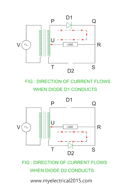
- As the end P of the secondary winding becomes positive with respect to T, the diode D1 forward biased and conducts.
- The load current flows through path P – D1 – Q – R – LOAD – U .
- The voltage across load is equal to voltage of the secondary half winding of the transformer neglecting voltage drop in the diode.
- The diode D2 remains in the reverse biased condition during positive half cycle of the alternating supply.
Voltage drop Silicon diode : 0.7 V
Voltage drop Germanium diode : 0.3 V
Negative half cycle
- As the end T of the secondary winding becomes positive with respect to P, the diode D2 forward biased and conducts.
- The load current flows through path T – D2 – S – R – LOAD – U.
- The voltage across load is equal to voltage of the secondary half winding of the transformer neglecting voltage drop in the diode.
- The diode D1 remains in the reverse biased condition during positive half cycle of the alternating supply.
We can say that the diode D1 conducts during positive
half cycle of the alternating supply and diode D2 conducts during negative half
cycle of the alternating supply.
Load current
- The direction of the load current is shown in the Figure.
Advantages of full wave rectifier
- Better ripple factor as compared to single phase half wave rectifier
- Efficiency high as compare to single phase half wave rectifier
Disadvantages of full wave rectifier
- The diode voltage rating must be high as peak inverse voltage is equal to twice voltage across the half secondary winding.
- Centre tapping transformer requires
You may also like :
Compare – Audio Amplifier & Tuned Amplifier
Compare – Voltage Amplifier & Power Amplifier


No comments:
Post a Comment