In
this theory, the working of single-phase full wave bridge rectifier is given.
Bridge Rectifier
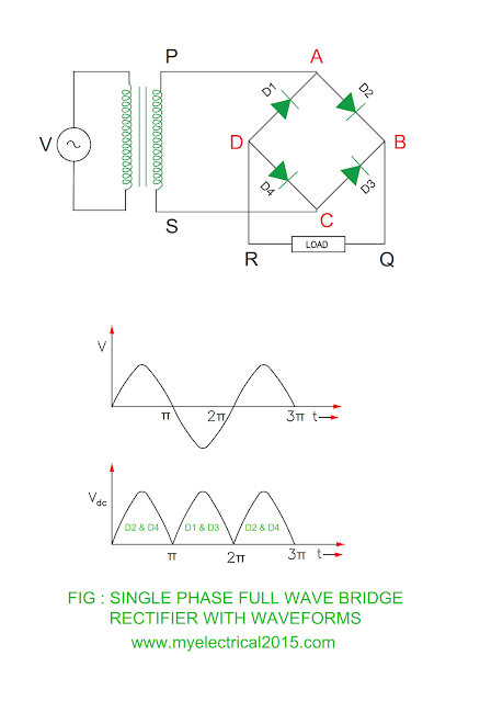
Bridge Rectifier Circuit Description
- There are four diodes D1, D2, D3 and D4 connected in the bridge configuration.
- There is no need of center tapping transformer as that is required in the single-phase half wave rectifier.
- The alternating supply through step down transformer is given to diagonally opposite end AC and load is connected to other two ends BD.
Working of Bridge Rectifier
Positive half cycle
- The end P of the secondary winding of transformer becomes P whereas S becomes negative during positive half cycle of the alternating supply.
- This will make diodes D2 and D4 forward biased and current flows through them.
- The current flowing through path P – A – D2 – B – Q – LOAD – R – D – D4 – C – S.
- As there are two diodes D2 and D4 conducts and both are in series, the voltage available at the load is equal to secondary winding voltage minus voltage drop in the diodes D2 and D4.
- The diode D1 and D3 remains in the reverse biased condition during positive half cycle of the alternating supply.
Load voltage = Transformer secondary
voltage
– Voltage drop across
diode D2
– Voltage drop across
diode D4
Voltage drop across diode = 0.7 V for
Silicon
= 0.3 V for Germanium
|
You may also like : Colour code of flexible and non – flexible cable Why crushed rock is used at the ground of the
substation? Important earthing rule as per IE 1956 |
Negative half cycle
- The end S becomes positive with respect to end P of the transformer secondary winding.
- This will make diode D1 and D3 forward biased and current flows through them.
- The current flowing through path S – C – D3 – B – Q – LOAD – R – D – D1 – A – P.
- As there are two diodes D1 and D3 conducts and both are in series, the voltage available at the load is equal to secondary winding voltage minus voltage drop in the diodes D1 and D3.
- The diode D2 and D4 remains in the reverse biased condition during positive half cycle of the alternating supply.
Load voltage = Transformer secondary
voltage
– Voltage drop across
diode D1
– Voltage drop across
diode D3
Advantages of Bridge Rectifier
- No need of centre tapping transformer
- The peak inverse voltage is one half to that of single phase full wave
- Rectifier
- Low ripple factor
Disadvantages of Bridge Rectifier
- Four diode requires
- There are two diodes conducts which are in series during positive and negative half cycle of the alternating supply.
- The output voltage is low as compared to single phase full wave rectifier because of voltage drop in the two diodes.
Why is it called as single-phase full wave bridge rectifier?
Single phase – The single-phase
supply is given at the input side
Full wave – Diodes conduct during
both positive and negative cycle
of the input supply
Bridge – Four diodes are connected in
the bridge configuration
Rectifier – It converts the input AC
power into output DC power.


No comments:
Post a Comment