In this post, methods of cable laying in the underground
cable are discussed. There are following methods of cable laying.
Direct
laying
Draw
in System
Cable Laying on rocks inside tunnel
Cable Laying Method in Underground
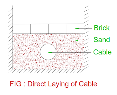
Direct Laying
- In this method of cable laying, a trench of about 1.5 meter deep and 45 cm wide is dug.
- The trench is covered with layer of sand of about 10 cm thickness and cable is laid over it.
- The sand prevents the entry of moisture from bottom side or ground.
- Once cable is laid over the sand, another layer of sand about 10 cm thickness laid above the cable.
- The trench is covered with brick in order to protect cable from mechanical injury.
- If more than one cable is laid in the trench, it is placed horizontally or vertically.
- There is axial spacing of 30 cm is provided between cables in order to reduce heating between them and fault on one cable does not affect other cable.
Minimum depth of laying of cable from ground surface to the top of the cable
|
Cable |
Clearance from top of ground to top
of cable |
|
High voltage cable : 3.3 kV to 11 kV |
0.9 m |
|
High voltage cable : 22 kV , 33 kV |
1.05 m |
|
Low voltage cable |
0.75 m |
|
Control cable |
0.75 m |
|
Cable at road crossings |
1.00 m |
|
Cable at railway crossings |
1.00 m |
Minimum Clearance for Power Cables & other Cables
|
Power cable to control cable |
0.2 m |
|
Power cable to gas / water main |
0.3 m |
|
Power cable to communication cable |
0.3 m |
Advantages of Direct Laying
- Simple method
- Less costly
- Better condition for dissipation of heat generated in the cable
- Cable is free from adverse effect of external atmosphere conditions
Disadvantages of Direct Laying
- Localization of fault is difficult
- Extension of load is only possible by costing of new excavation and cable laying
- High maintenance cost
- It cannot be used in the congested area where excavation is inconvenient and expensive.
- Cable may be damaged due to frequent digging at the place of cable laying
- The lead sheath of cable may be damages due to chemical changes in the soil.
Draw in System
- This method is adopted in the congested area where direct laying of cable is expensive.
- In this method of cable laying, a line of conduits, duct or tube made of either iron or stone / cement concrete are laid in the trenches side by side.
- The cable is pulled in the manholes.
- Figure shows four way underground duct line for cable.
- Out of four duct, three duct carries main power cable and fourth duct carries control cable for protection and switchgear equipment.
- The diameter of duct pipe should always be larger than the diameter of cable in order to pull cable safely.
- The duct always made straight but sometimes it is made curved if any obstacles.
- When duct is made curved, the diameter of pipe is made kept larger to facilitate drawing cable through pipe.
- The vertical distance between two adjacent pipes should be 0.25 m – 0.75 m.
- The cable need not be provided armouring but provided with serving of jute / hessian tape in order to protect them during draw in duct.
Advantages of Draw in Laying
- Repair / maintenance of cable is possible without excavation of ground
- Maintenance cost is considerably reduced as compared to direct laying of cable method
- Less chances of fault occurrence between cable due to mechanical protection provided by the duct pipe.
- Long life of cable due to less chances of fault on cable
Disadvantages of Draw in Laying
- High initial cost
- The current carrying capacity of cable is reduced due to less heat dissipation and close grouping of cables.
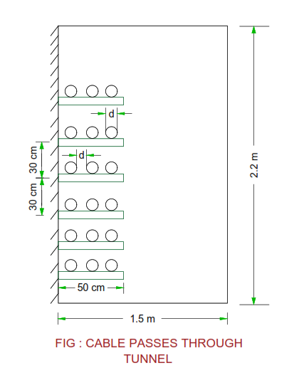
Cable Laying on rock inside tunnel
- The laying of cable on racks is shown in the figure.
- If the tunnel is unventilated, the heat generated in the cable is dissipated only through the wall of tunnel.
- Therefore there is an increase in the temperature of cable inside tunnel resulting current carrying capacity of cable is derated in the tunnel.
- The increase in temperature in the tunnel is given by
T = W / 3P
Where
T = Temperature in 0C ( above ambient
temperature )
W = Heat loss per meter length of cable ( watt )
P = Perimeter of tunnel cross section in meter
Cable Suspended from Catenary Wire
- In some area, the cable is suspended by means of aluminum / steel / leather suspenders.
- The suspender is hung from catenory wire by means of galvanized iron wire.
- The catenary wire is made of galvanized steel of adequate strength.
- The two ends of catenary wire should be connected to rigid supports. The rigid supports may be of steel poles.
You may also like :
Compare Power Transformer – Distribution Transformer
Tertiary winding : Construction and Working
Earthing Transformer : Construction and Working
Hysteresis Motor : Construction, Working,
Characteristic, Applications
Reluctance Motor : Construction, Working, Characteristic, Applications


No comments:
Post a Comment