Significance
- The No test on the single phase transformer is performed in order to find out no load parameters of the transformer.
- This test is performed to find out
- No load current
- Magnetizing current
- Loss component of no load current
- No load
equivalent circuit parameters : Exciting susceptance B0 and Exciting
conductance G0
- Iron loss and small amount of copper loss
- Voltage transformation ratio
Instruments
required
AC voltmeter :
__________
AC ammeter : __________
Wattmeter : ___________
Multi meter : __________
Theory
- The single phase transformer consists of mainly high voltage winding and low voltage winding.
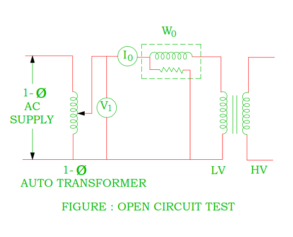
- The high voltage winding is kept open circuited whereas the single phase supply is given to the low voltage winding.
- The supply is given as per rating of the transformer. As the normal voltage is given to the primary winding, normal flux sets up in the core of the winding.
- The no load current is only 2 to 5% of the full load current therefore the wattmeter indicates iron loss plus small amount of copper loss.
- The no load current of the transformer consists of two components : magnetizing current and loss component of the no load current.
- The function of the magnetizing current is to create flux in the core where the function of the core loss component of the no load current is to supply small amount of copper loss plus iron loss.
Circuit diagram
Procedure
- Make connection as per circuit diagram.
- Switch on the supply and note down the reading of voltmeter, ammeter and wattmeter.
Observation
table
|
Supply voltage |
No load current |
Wattmeter reading |
Secondary voltage |
|
V0 |
I0 |
W0 |
V2 |
|
|
|
|
|
|
No load input Power |
W0 = V0 I0 Cos Φ0 |
|
|
No load input power factor |
Cos Φ0 = W0 / V0 I0 Φ0 = Cos – 1( W0 / V0 I0 ) |
|
|
Magnetizing current |
Iµ = I0 Cos Φ0 |
|
|
Loss component of no load current |
Iw = I0 Sin Φ0 |
|
|
Exciting admittance |
Y0 = I0 / V0 |
|
|
Exciting conductance |
G0 = W0 / V02 |
|
|
Exciting susceptance
|
B0 = √ ( Y0 )2 – ( G0 )2 |
|
|
Voltage transformation ratio |
k = V2
/ V0 |
|
The no load
current is only 2 to 5% of full load current.
Questions
Why the no load
current is very small as compared to full load current in the transformer?
- The core of the transformer has very low reluctance path therefore the no load current is 2 to 5% of the full load current.
Why the copper
losses are neglected in the open circuit test of the transformer?
- The no load current is only 2 to 5% of the full load current and no flow of current through secondary winding of the transformer therefore the copper losses are neglected in the transformer.
Which winding is
kept open circuited of the transformer winding? High voltage or Low voltage
The high voltage
winding is kept open circuited in the single phase transformer due to following
reasons.
- Low voltage supply is easily available from practical point of view.
- The no load current of low voltage winding is high as compared to high voltage winding which is measurable.
How the iron
losses are calculated from the open circuit test of the transformer?
- The wattmeter reading indicates combined iron losses and copper loss of the transformer.
- If we neglect copper loss, the wattmeter indicates total iron losses of the transformer.
- However the copper loss of the primary winding is calculated as below.
- Measure primary winding reading by voltage – current method or multi meter.
- The copper loss of the primary winding is I12R1.
- Iron loss = Wattmeter reading – Copper loss of the primary winding = W0 – I12R1
You may also
like :
How to separate out hysteresis loss and eddy current loss in the DC Machines?
Compare BLDC Motor and Conventional DC Motor
To perform brake test on DC Series Motor
To perform Swinburne Test on DC Shunt and DC Compound Motor


No comments:
Post a Comment