Characteristics of SCR
In this post, static and dynamic characteristic of SCR is given. The static characteristic is related to voltage – current relation of the SCR during on state whereas the dynamic characteristic is related to current and voltage across SCR during its ON state and OFF state.
Static Characteristics of SCR
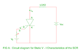
- Figure A shows the circuit diagram to obtain V – I characteristic of the SCR.
- Here VAK is voltage between anode to cathode and Vg is gate voltage.
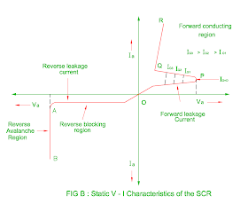
- The static V – I characteristic of the SCR is divided into following mode.
Reverse Blocking Mode
- When cathode is made positive with respect to anode and gate switch is kept open circuited, junction J1 and J3 are reverse biased whereas the junction J2 becomes forward biased.
- Hence only small leakage current flows through the device.
- If the anode voltage increases to certain level, an avalanche break down occurs at the junction J2 and current flows sharply through all the junctions.
- This current is limited to safe value in order to protect SCR due to high power dissipation.
- The region OA is known as reverse blocking mode and AB is known as reverse avalanche breakdown mode of the SCR.
Forward Blocking Mode
- When anode is made positive with respect to cathode and
switch S is kept open circuited, junction J1 and J3 are forward biased whereas
the junction J2 become reverse biased.
- This will result in only small
leakage current flows through the device.
Forward
Conducting Mode
- When anode to cathode voltage increases to
certain level say threshold voltage, an avalanche breakdown occurs at junction
J2 and device comes in to conduction state ( region PQ ).
- The voltage
across SCR drops from several thousand voltage to few voltage and current
increases sharply in the forward conducting state.
- When the gate signal is
applied, SCR is turned on before forward break over voltage is reached.
- Higher
the gate current, lower the forward break over voltage.
- Figure B shows
different value of gate current and corresponding break over voltage.
- Once the
SCR conducts, it remains in conducting state in spite of gate signal
removes.
- The SCR will turn off only when the forward current is reduced
below holding
current.
Dynamic
Characteristics of SCR
Dynamic Characteristics of SCR
- The switching action does not take place
instantaneously but it will take some finite time.
- We will discuss turn on and
turn off switching characteristic of the SCR in this section.
SCR Turned ON
Time ( ton )
SCR Turned ON Time ( ton )
Turn on time ( ton )
- The turn on time of the SCR is defined as the
time during which the SCR changes from forward blocking state to forward
conducting state.
- The total turn on time of the SCR is divided in to two
intervals : Delay time and Rise time
ton = td + tr
Delay time ( td )
- It is time duration from the instant at which
the gate current reaches 90% of its final value to the instant at which anode
current reaches 10% of its final value.
OR
- It is defined as time during which anode
voltage falls from VA to
90% of VA.
OR
- It is defined as time during which anode
current rises up to 10% of final value from forward leakage current.
- The
delay time can be decreased by applying high gate current and more forward
anode to cathode voltage.
Rise time ( tr )
- It is defined as time during which anode
current rises from 10% to 90% of final value.
OR
- It is defined as the time required for the
forward off state voltage reduces form 90% to 10% of initial value.
- The rise
time is reduced by applying high and steep gate pulses.
- However the rise
time depends upon the nature of the anode current i.e. The rise time is less
for RC circuit and more for RL circuit.
- The total turn on time is given in
the range of micro second.
- The actual turn on time of the SCR is much
higher than the turn on time given in the manufacturer’s data sheet.
SCR Turned OFF Time
( toff )
- Once the SCR start to
conduct, gate loses control.
- The SCR can be turned off by reducing the
anode current below holding current for sufficient time.
- This can be
achieved by natural commutation or forced commutation.
- The turn off time
of the SCR is defined as the time interval between the instant at which the
anode current becomes zero and the instant at which SCR regain forward blocking
voltage.
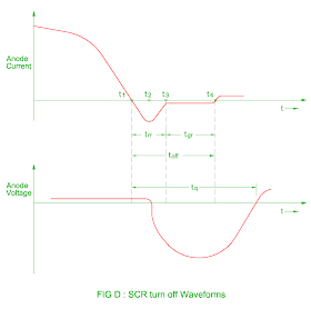
- The total turn off time can be divided in to two intervals :
reverse recovery time ( trr )
and gate recovery time ( tgr )
- The anode current becomes zero at instant t1.
- The anode current flows in the opposite direction during reverse recovery time ( t3 – t1 ).
- The reverse anode voltage developed across the SCR at the instant t2 and reverse current continue to decrease.
- Therefore the reverse recovery time is defined as the time between the current reversal and the instant at reverse current has decayed to 10% of negative peak value.
- The reverse recovery time increases as the forward current increases.
- When the reverse recovery current stops, high transient voltage appears across the SCR which may damage it.
- The middle junction J2 contains charges which must decay only by recombination at the end of reverse recovery time.
- This recombination is possible if a reverse voltage is maintained across the SCR therefore the time for recombination of charges ( t3 – t4 ) is called as gate recovery time tgr.
- The recombination is stopped at time t4 and forward voltage can be reapplied at time instant.
- The turn off time of the SCR is given is in the range of 3 to 100 micro second.
- The circuit turn off time must be greater than the SCR turn off time in actual practice.
- Therefore the circuit turned off time tc is defined as the time between the instant anode current becomes zero and at the instant reverse voltage becomes practically zero.
- The circuit turned off time tc must be greater than the SCR turn off time otherwise the SCR may turn on at undesired instant and it is known as commutation failure.
- The turn off time increases with increase in the magnitude of anode current and junction temperature.
- It also depends upon type of commutation circuit i.e. natural commutation or forced commutation
You may also like :
Interview Question Answer – Design of Transformer 1
Interview Question Answer – Design of Transformer 2
Interview Question Answer – Design of Transformer 3
Interview Question Answer – Design of Transformer 4
Interview Question Answer – Design of Transformer 5
Interview Question Answer – Design of Transformer 6


please suggest how can i download this doc.
ReplyDeleteyou can directly copy and paste it
DeleteHello sir .its written that OA is forward blocking mode under the heading reverse blocking mode not justifying the image
ReplyDeleteyes , you are right it is bymistake
ReplyDelete