The following are main parts of DC machine.
Figure A shows the construction of the 2 – Pole DC machine.
Yoke or Frame
- The main function of the yoke is to provide protection for whole machine.
- The yoke is a stationary and outer cylindrical part of DC machines.
- The cheapness is main consideration therefore yoke is made up of cast iron in the small DC machines but it is made up of cast still or rolled still in the large DC machines.
- The function of
the yoke is to (1) Carry the magnetic flux produced by the poles (2) To provide support for
main poles and inter poles (3) To provide protection for whole machine
What is advantage of using cast steel for yoke
material?
- The yoke was made up of cast iron earlier but now it is replaced by cast steel.
- This is due to fact that cast iron is saturated by a flux density of 0.8 Weber / meter2 whereas the saturation flux density of cast steel is about 1.5 Weber / meter2.
- Therefore the working flux density of cast steel is approximately twice than that of cast iron.
- Thus the cross section area and hence weight of cast steel is one half that of cast iron.
- The mechanical and magnetic properties of cast iron are uncertain due to blow holes in the material.
Pole Cores and Pole Shoes
- The pole cores are made up of either cast iron or cast steel.
- The poles are secured to the yoke by means of screws bolted through the yoke. The pole cores are either laminated or solid piece.
- The thickness of pole cores laminations may be 0.4 mm - 0.5 mm in large size DC machines.
- The pole cores and pole shoes are built of these laminations of annealed steel.
- To Support the field winding
- To spread out the flux in the air gap and also reduces the reluctance of the magnetic path.
Field coils or Pole coils
- The poles are surrounded by the field coils.
- The field winding is in the form of the copper wire or rectangle strips.
- The number of ampere – turns of the field winding is required to required proper flux which induces the desired voltage in armature winding.
- When the field coils are excited by DC supply, the flux passes through pole, air gap, armature and yoke ( or frame ) of DC machines. ( Figure A ).
Armature
- It houses the armature conductors.
- When an armature is rotated in the magnetic field, its function is to provide low reluctance path to the magnetic flux.
- The armature core is made up of thin laminations of low loss silicon steel.
- Each lamination is about 0.5 mm thick.
- The laminations are punched in single piece and it is directly keyed to shaft in the small machines.
- Some ventilating ducts are provided on lamination sheets to permit axial flow of air for cooling purposes.
- It is not economical to punch the laminations in one piece in the large machines so it is made in segments.
- Each laminations have dove – tailed or wedge – shaped which are keyed into spiders.
Armature winding
- The different shape of slots in which armature winding is housed is shown in the Figure F.
- The conductors of coils are insulated from each other by enamel ( Insulating material ).
- The armature coils are secured by placing wood or fibre wedge in the slots.
Commutator
- The function of the commutator is to collect current from the armature coils and converts the alternating current into unidirectional current for the external load circuit.
- Each coil of armature winding is connected to commutator bar therefore the number of commutator segments are equal to number of coils.
- The armature conductors are connected to the commutator with the help of risers.
- The commutator segments are made from silvered copper ( copper + 0.05% silver ).
- The advantage of silvered copper material is that it can withstand very high temperature when the armature coil ends are soldered to commutator risers.
- The commutator segments are wedge shaped and each segments are insulated from each other by thin layers of mica ( Usually 0.5 to 0.8 mm thickness ).
- The commutator segments are wedge shaped and each segment is held together by means of V – shaped steel rings.
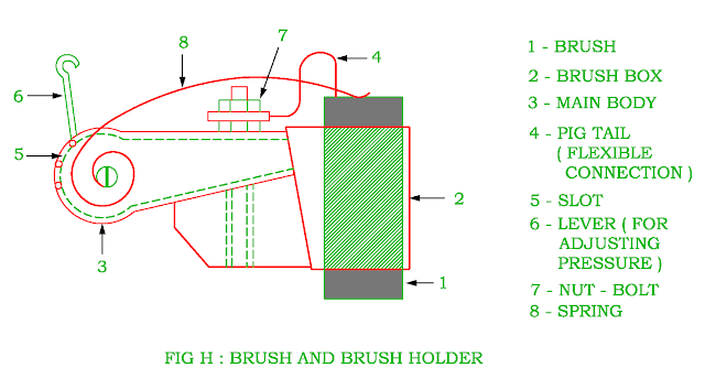
Brush and Brush Holder
- The function of the brush is to collect current from the commutator for the external circuit.
- The brushes are made up of hard carbon or metal and are in the shape of rectangle which are metal box type.
- The pressure on the brush can be adjusted by a spring whose tension can be adjusted by changing the position of brush lever as shown in the Figure H.
- The copper wire which is connected to brush is called as " Pig – tail ".
- The number of brushes per spindle depends upon the magnitude of current to be collected.
Bearings
- The armature is mounted on the mild steel shaft which is supported between two bearings.
- The bearing may be sleeve, ball or roller type and they are normally lubricated by oil or Grease.
You may also like :


Hi
ReplyDeleteGood article and use different contents.
Thanks for sharing this article and your information.
https://www.rushitechniques.com/