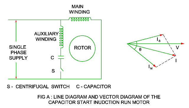
Capacitor Start
– Induction run Single Phase Motor
- The phase difference between main winding and starting winding is achieved by introducing an electrolyte capacitor is in series with starting winding.
- The capacitor is electrolyte type. When the speed of the motor is increased 70 to 80% of full load speed, the centrifugal switch open and starting winding is cut out.
Vector
diagram
- As the capacitor is in series with starting winding, its vector IS leads supply by some angle.
- The current vector IM lags the supply voltage by some angle ( < 900 ) due to high inductance of the main winding.
- The angle between current vector IS and IM is in the range of 800 to 900 which is nearly 300 in the case of Split phase motor.
Starting
torque
- The starting torque is directly proportional sine of angle between starting current and main current.
T a
( Sin θ )
- The starting torque in the capacitor start – induction run motor is about 3.5 to 4 times that of full load torque.
Advantage of Centrifugal switch over Magnetic switch
- It is not
affected by the line voltage
- More reliable
- Low cost
Electrolyte
Capacitor
- It is formed by
winding two sheets of etched aluminum foil and separated by two layers of
insulating layer in the shape of cylindrical.
- This whole unit is impregnated
with an electrolyte of ethylene glycol.
- An anodic film is produced on each foil
by the electro – chemical action.
- The voltage rating of the capacitor should
not necessary be same as that of motor rating.
- The power factor of the such
capacitor is in the range of 6 to 8 %.
Speed Regulation
- The speed of the
motor varies 10% to 100% from no load to full load
Rating
- It is available
in the range of 1/6 HP to 3 HP.
Application
- Compressors
- Elevators
- Conveyors
You may also like :
Neutral Shifting in the Transformer
Auto transformer working and Saving in Copper
Armature Reaction in the DC Generator
Compare Power Transformer - Distribution
Transformer
Function of Dummy coils
Auto transformer working and Saving in Copper
Armature Reaction in the DC Generator
Compare Power Transformer - Distribution
Transformer
Function of Dummy coils


No comments:
Post a Comment