- The process of joining two metal plates is called as resistance welding.
- The step down transformer is used to pass current through two metal plates.
- The mechanical pressure is given to two metal plates between two electrodes as shown in the figure A.
- The metal plates get damage if the mechanical pressure is too excessive. The time duration and current requires for the welding depends upon following factors.
2. Resistivity of metal
3. Thermal conductivity of metals
- When current passing through metal plates, the heat is produced due to current passing through it resulting the process of welding is done. The heat generates due to welding is
Where I = Instantaneous current
r = Resistance of
metal plates
t = Time duration of
welding
Electronic Control in Resistance Welding
Electronic Line contactor
- The current requires for the welding process is done by contactor.
- The electro mechanical contactor has following disadvantages.
1. Heavy arc generates
when contactors are separated
2. High maintenance
3. Slow operation
- There are two SCRs connected in back to back parallel in order to control alternating positive and negative half cycle.
- The transient voltage is generated due to switching of SCRs again and again. This voltage may damage the transformer primary winding.
- A thyride resistor is connected across transformer primary winding in order to suppress transient voltage. When there is cooling water, the contactor W closed and vice versa.
W = cooling water
contactor
T = Welding
transformer and
K = Control contactor
Positive half cycle
- The control current flows when contactor K and H both are on during positive half cycle of alternating supply.
- The control current flows through path A – B – C – D3 – W – F – K – D2 – G2 – K2 – D. The SCR 2 receives gate signal and resulting it turns on therefore the load current flows through path A – B – C – A2 – K2 – D.
Negative half cycle
- Similarly the control current flows through path D – D4 – K – F – W – D1 – G1 – K1 – C – B – A.
- The SCR 1 receives gate signal and resulting it turns on therefore the load current flows through path D – A1 – K1 – C – B. The low gate current controls the high load current in this way.
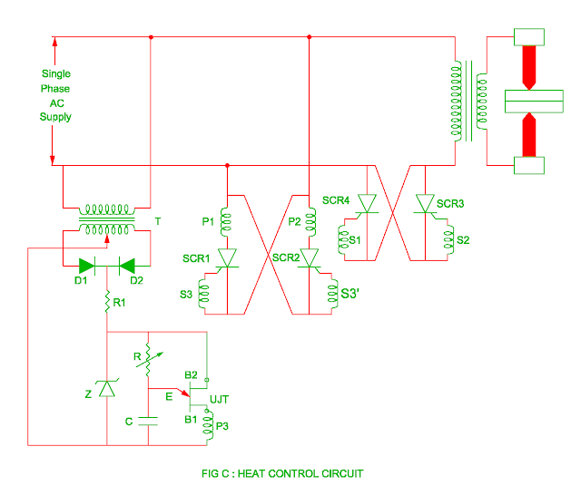
Heat control
- The heat generates during resistance welding is
- The heating control depends upon resistance of metal contactor, time of operation and welding current.
- The good welding quality depends upon time of operation and welding current. The current to be control depends upon firing angle of SCR.
- The control current increases as the firing angle of SCR decreases and this will generate large heat. The firing angle of SCR is controlled by following ways.
- The SCR 1 and SCR 2 are controlled SCR whereas SCR 3 and SCR 4 are main SCRs.
- There are three pulse transformers P1, P2 and P3 in which pulse transformer P3 has two secondary winding S3 and S3’.
- The step down transformer provides necessary voltage for diode D1 and diode D2.
- The zener diode Z clips the rectified output and therefore the RC circuit receives constant DC voltage.
- The charging rate of capacitor depends upon variable resistor R.
- When the voltage across capacitor becomes peak voltage of UJT, the UJT turns on.
- The discharging of capacitor is done through path C – E – B1 – P3 – C path.
- As soon as the UJT turns on, the secondary S3 and S3’ of pulse transformer receives pulse resulting SCR 1 and SCR 2 are turned on during negative and positive half cycle of alternating supply.
- As the SCR 1 and SCR 2 are turned on, the current passes through pulse transformer P1 and P2.
- The SCR 3 and SCR 4 are turned on by gate pulse S1 and S2. The firing angle of SCR are adjusted by variable resistor R.
- The firing angle of SCR 3 and SCR 4 decreases if the resistor R is kept at low value.
- This will result in high current and more heat is produced. Similarly if the variable resistor R is kept at high value, the firing angle of SCR increases. This will result in current and heat decreases.
You may also like :


